The purpose of a power supply is to take an A.C. input voltage - such as the mains electricity - and produce a lower output voltage.
This lower output voltage is usually converted to D.C. To learn more about A.C. and D.C. see the analogue signals page.
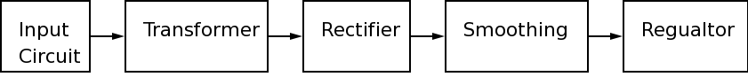
The basic block diagram for a power supply is shown below
The input circuit connects the power supply to the mains electricity supply.The Live and Neutral connections provide power and the Earth connection is connected to the metal casing of the power supply unit. The input circuit contains a fuse, a switch and (usually) an indicator to show the power supply is on.
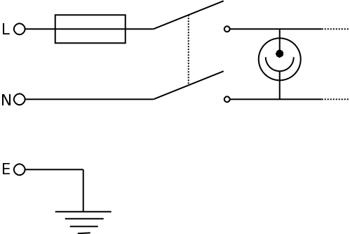 The Fuse - protects the power supply from faults. If a fault occurs and too much current flows then the fuse blows. The fuse is often a 'slow blow' type that can withstand the initial current surge as the smoothing capacitors charge up for the first time.
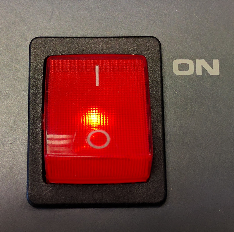
DPST switch - ideally a double pole switch is used to turn the power off. The switch may incorporate a neon bulb. The switch should be of a suitable current rating for the power supply.
The switch and the fuse are always in the LIVE wire.
Neon indicator - a neon indicator (a) works at a high voltage and (b) is very reliable. This makes it ideal as the warning indicator to show that the power supply is on.
The transformer converts the 240V A.C. mains to a lower A.C. voltage.
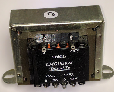
 The transformer converts the high mains voltage to a lower, more useful voltage.
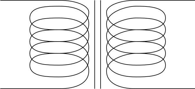
A transformer consists of a primary coil and a secondary coil wound on a laminated iron core. The transformer equation determines the number of turns on the primary and secondary that are required to give a particular output voltage. If the secondary voltage is lower than the primary voltage (as is usually the case) then the primary current will be lower than the secondary current. This is important to remember when determining an appropriate value for the fuse.
The transformer equation is:
The rectifier converts the low voltage A.C. into 'rough' low voltage D.C. In the diagram below the secondary of the transformer is connected to a diode. The A.C. output of the transformer is the red line on the graph. The diode only allows the current to flow when the voltage from the transformer is positive and the diode is forward biased. The output from the rectifier is shown by the blue line on the graph.
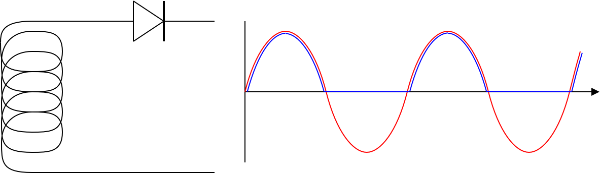 The rectifier diode only allows current to flow each half cycle. Current only flows in one direction i.e. it is D.C.
This is the most simple type of rectification but it is not very efficient as only half the available power is used. The output voltage from the rectifier is 0.7 V less than the output from the transformer. This is the voltage drop across the rectifier diode.
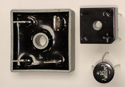
A full wave rectifier is more complex to build as it requires four diodes. The advantage is that each half of the A.C. from the transformer is rectified and so less power is wasted. The A.C. output of the transformer is the red line on the graph. The pairs of diodes only allow the current to flow in one direction but on both halves of the cycle. The output from the rectifier is shown by the blue line on the graph.
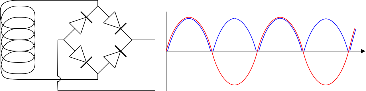 The rectifier diodes allow current to flow in both halves of the A.C. cycle. Only two of the diodes allow current to flow at any one time. The current still only flows in one direction i.e. it is D.C.
Full wave rectification is efficient as all the A.C. power is rectified. The output voltage from the rectifier is 1.4 V less than the output from the transformer. This is the voltage drop across the two rectifier diodes.
The smoothing circuit uses a capacitor makes the 'rough' D.C. from the rectifier into a smoother low voltage D.C. In the diagram, the green line is the voltage across the capacitors - on each half cycle of the A.C. the voltage reduces, but not to zero.
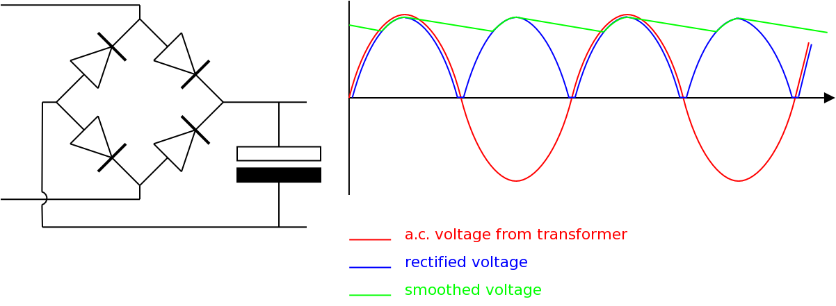 The rectified D.C. voltage is smoothed by a capacitor. The capacitor charges up as the voltage rises and then slowly discharges whilst the rectified voltage falls back to zero. The value of the capacitor has to be large enough to supply current until the rectified voltage rises again.
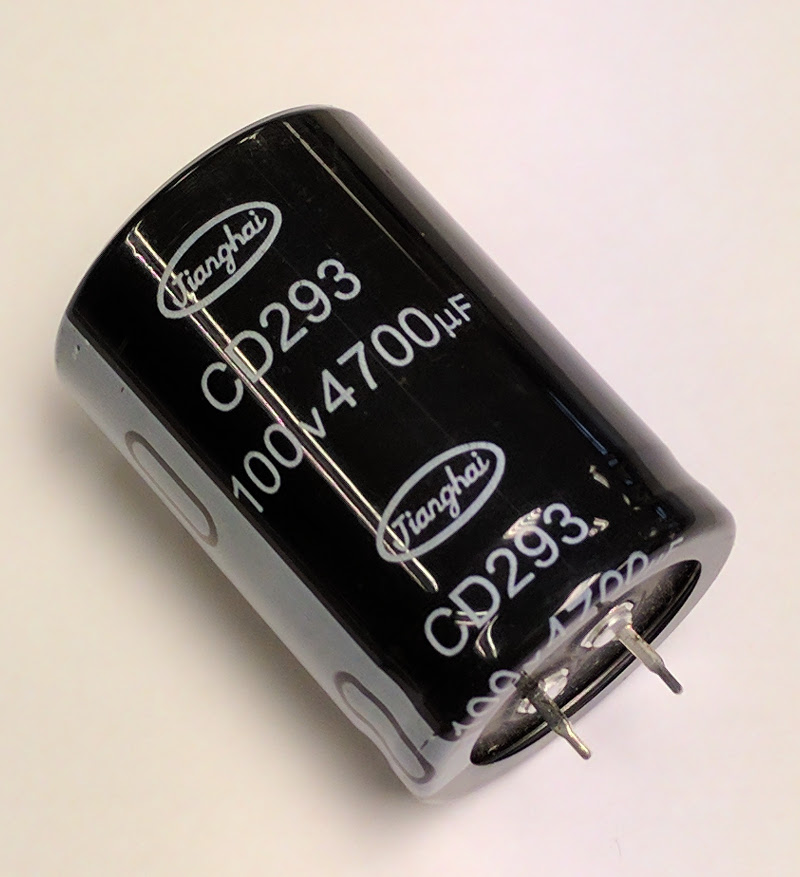
The voltage rating of the capacitor depends on the peak value of the rectified supply voltage. The maximum working voltage of the capacitor must be greater than the peak output voltage from the rectifier.
The capacitance of the smoothing capacitor depends on the current requirements of the power supply. If more current is required, the capacitor will discharge more quickly and so a bigger capacitor is needed to maintain a steady voltage. Large electrolytic capacitors are used as smoothing capacitors.
The regulator keeps the output voltage at a steady constant level.
 The voltage regulator keeps the voltage output at a steady fixed voltage
The regulated voltage has to be below the lowest level of the smoothed voltage
Voltage regulators are often a single IC which is mounted on a heat sink.
For information about regulator ICs see the voltage regulator page.
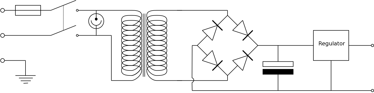
To build a simple power supply, the following circuit can be used
© Paul Nicholls
November 2015

Electronics Resources by Paul Nicholls is licensed under a Creative Commons Attribution 4.0 International License.