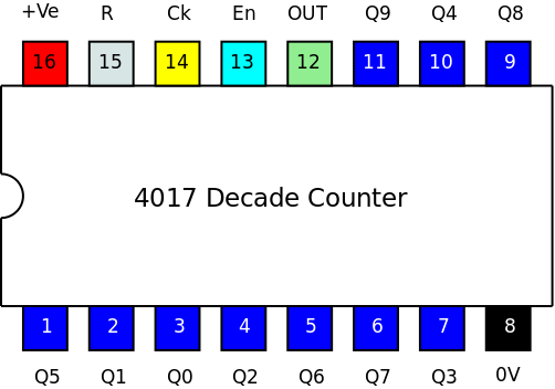
 The 4017 Decade counter is a device that counts clock pulses. It is called a decade counter because it has 10 outputs (Q0 to Q9) and so it can count 10 clock pulses before starting again. This is a very simple counter that is easy to understand and straightforward to use.
There are 10 outputs labelled Q0 to Q9. There is only ever one and only one output on at a time. Only one of the outputs will be HIGH and all of the other outputs will be LOW.
The CLOCK input (Ck) makes the output change each time the clock input goes from LOW to HIGH. The outputs change on the rising edge of the clock input. When the clock rises, the HIGH output goes LOW and the next output changes from LOW to HIGH.
The RESET (R) makes Q0 go HIGH and Q1 to Q9 go LOW. The RESET is usually LOW and will make Q0 go HIGH when RESET goes HIGH. When RESET is HIGH, Q0 is HIGH and all other outputs are LOW and the CLOCK has no effect - the counter will not count and the outputs will not change.
The ENABLE (En) is usually held LOW. When the ENABLE is HIGH the CLOCK has no effect and the outputs are fixed. The counter stops counting when the ENABLE is HIGH and the outputs do not change. The ENABLE is sometimes called the CLOCK INHIBIT which is a more descriptive name.
The ÷10 output (OUT) is HIGH when Q0 to Q4 are HIGH and OUT is LOW when Q5 to Q9 are HIGH. Therefore OUT is HIGH for half the counts and LOW for half the counts. OUT gives an output at 1/10th the frequency of the CLOCK pulses. Hence it is a ÷10 output. The OUT is also called the CARRY because it goes HIGH when the Q0 goes from LOW to HIGH and this rising edge can be used to provide the clock pulse for another counter - the count can be carried from one counter to the next.
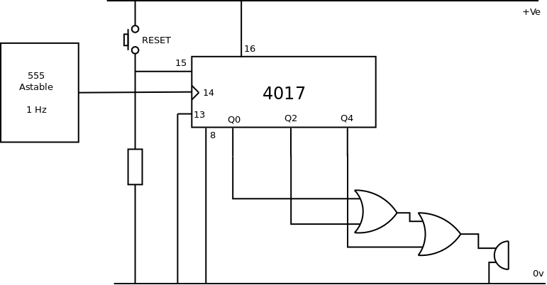
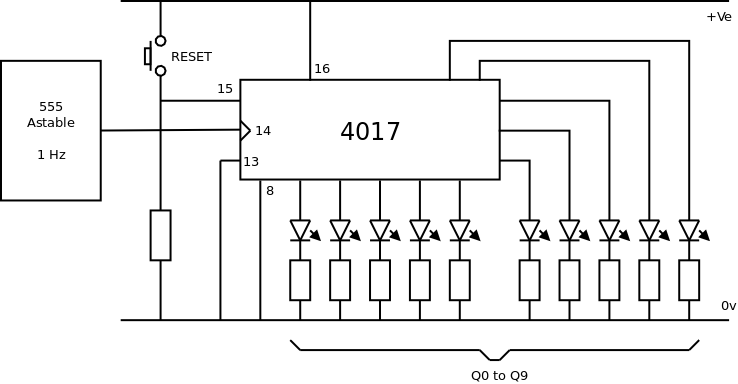 Pin 13 (En) is connected to ground (LOW) so that the 4017 will count the clock pulses.
The astable provides clock pulses and the outputs are shown by the LEDs. It is possible to use a push button and pull down resistor to provide clock pulses but each press of the button tends to produce multiple pulses as the push button bounces and so the counter sometimes appears to be giving a random count.
Pin 15 is the RESET which is held LOW with the pull down resistor until the reset button is pressed connecting RESET to HIGH.
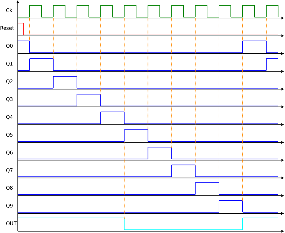 Initially RESET is HIGH and so Q0 and OUT are both HIGH and all other outputs are LOW.
On the rising edge of the 1st CLOCK pulse Q0 goes LOW and Q1 goes HIGH.
On the rising edge of the 5th CLOCK pulse Q4 goes LOW and Q5 goes HIGH and OUT goes LOW.
On the rising edge of the 10th CLOCK pulse Q0 goes HIGH again and OUT goes HIGH again.
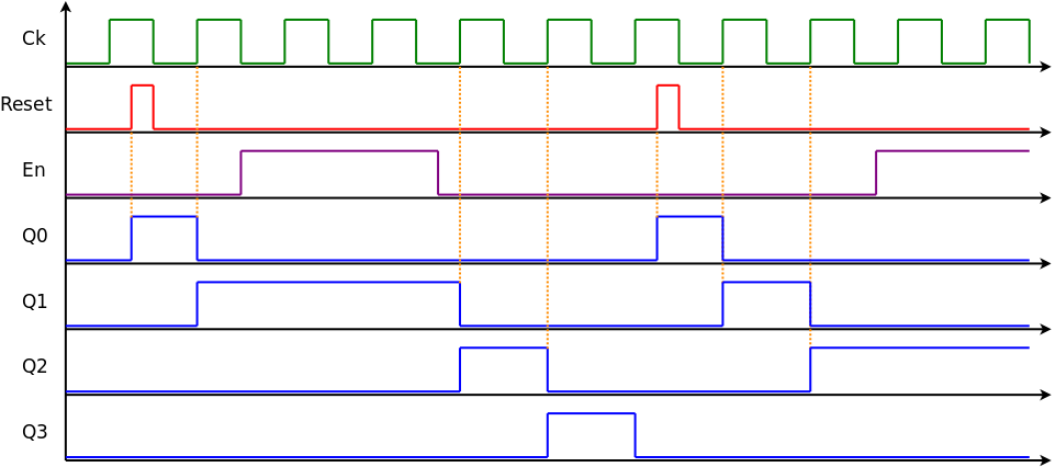 On the rising edge of the first clock pulse one of the outputs that is not shown changes state. However, when the RESET goes HIGH Q0 goes HIGH. On the rising edge of the next clock pulse Q0 goes LOW and Q1 goes HIGH.
Before the next rising edge of the CLOCK input, ENABLE is made HIGH and subsequent clock pulses have no effect - the outputs do not change state and Q1 stays HIGH. When ENABLE goes LOW the output does not change until the next rising edge of the CLOCK.
Subsequent clock pulses now advance the output to Q2 followed by Q3 and Q4 (not shown).
Another RESET pulse forces Q0 to go HIGH. The next two clock pulses advance the output to Q1 and then Q2.
Whilst Q2 is HIGH and before the next clock pulse ENABLE is made HIGH and the output is fixed with Q2 being HIGH.
 6 counts instead of 10:
Initially Q0 is HIGH and the LED is illuminated. On the first clock pulse Q1 goes HIGH and the next LED is illuminated. On each subsequent clock pulse the next output goes HIGH and the corresponding LED illuminates.
Q6 is connected to the RESET and this holds the RESET LOW for the first 5 clock pulses. On the 6th clock pulse Q6 goes HIGH and so the RESET goes HIGH and immediately rests the 4017 so that Q0 goes HIGH. Note that Q6 only remains HIGH for a fraction of a second whilst the IC resets. One (and only one) of the 6 LEDs will always be illuminated with the entire cycle repeating every 6 seconds due to the 1Hz clock frequency.
 Sequence of beeps:
Initially the circuit is reset using the push button meaning Q0 is HIGH and the output from the cascaded OR gates is HIGH. As the subsequent clock pulses are counted the output of the OR gates becomes HIGH again when Q2 is HIGH and when Q4 is HIGH. Therefore the circuit will produce a pattern of sounds that goes beep - space - beep - space - beep - long space (Q5 to Q9) and then repeats.
Other sound sequences can be produced using different combinations of OR gates to combine the outputs from the counter.
 Counts to 5 and stops:
In all other circuits the ENABLE (pin 13) has been connected to ground making it LOW so that the 4017 can count. In this circuit the ENABLE is connected to Q5 which forces it to be LOW and allows the counter to count.
Initially the circuit is reset using the push button and Q0 is HIGH and, crucially, Q5 is LOW. None of the LEDs are illuminated. The counter responds to each successive clock pulse and each LED illuminates in turn.
On the 5th clock pulse Q5 goes HIGH, the LED illuminates and ENABLE goes HIGH. This prevents the counter from responding to any further clock pulses. The 5th LED remains illuminated until the circuit is reset. The circuit counts from 1 to 5 and then stops counting leaving the 5th LED illuminated.
© Paul Nicholls
July 2016

Electronics Resources by Paul Nicholls is licensed under a Creative Commons Attribution 4.0 International License.