 The 4510 is a counter. The full name of the counter is a Divide by 10 BCD Up-Down Counter
The divide by 10 part means it counts 10 (0 to 9) clock pulses before starting again
BCD stands for Binary Coded Decimal. The output is in binary but only counts from 0 to 9 before starting again
Up-Down means the counter can either count up from zero or down from 9
The advantage of a BCD counter is that it can be used to make a decimal counter (1's, 10's, 100's etc) without the need for further logic as the counter automatically resets to zero on the tenth clock pulse. The counter gives a binary output of the decimal number system.
There are four outputs Q1, Q2, Q4 and Q8. The output is in binary where Q1 = 1, Q2 = 2, Q4 = 4 and Q8 = 8. In the most basic configuration, Carry In (CI), Reset (RST) and LOAD are held LOW by connecting them to 0 V. The binary number represented by the four outputs increases or decreases by one on each rising edge of the clock (Ck) pulse. The value of the Up-Down (U/D) input determines whether the count increases or decreases.
The 4510 is a BCD counter. The outputs count from Zero to Nine in binary and then start again at Zero when counting up and vice versa when counting down.
Making Reset HIGH will make all the outputs LOW, resetting the output to binary Zero.
A binary number can be loaded into the counter using the load lines L1, L2, L4 and L8. L1 to L8 are connected either HIGH or LOW depending on the binary number required and then the LOAD input is made HIGH momentarily. The value on the load lines is transferred to the outputs. This is useful to make a counter that counts from ONE rather than from ZERO for instance.
The Carry Out (CO) is usually HIGH but goes LOW when the counter is about to Carry. This means that CO goes LOW when the Output is binary NINE if the counter is counting up. If the counter is counting down, CO goes LOW when the Output is binary ZERO. In either case, the CO divides the clock frequency by 10 hence a 'divide by 10' counter.
Two counters may be connected together (cascaded) by connecting the Carry Out (CO) of the first counter to the Carry In (CI) of the second counter and connecting both counters to the same clock. Carry In of the first counter should still be connected LOW.
Carry In (CI) can be used as a clock enable. When Carry In is held HIGH, the clock is ignored. When Carry In is held LOW, clock pulses are counted.CI can also be thought of as Clock Inhibit because it prevents clock pulses from being counted.
The Up-Down input (U/D) determines whether the count increases or decreases with each clock pulse. The counter counts Up when U/D is HIGH and the counter counts Down when U/D is LOW.
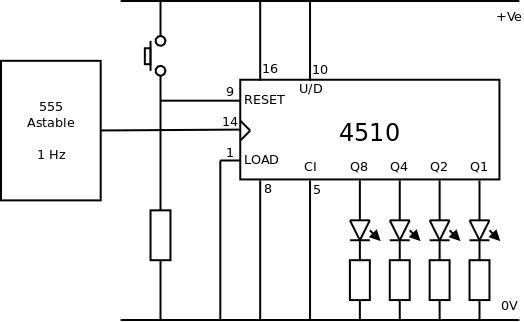 The most basic configuration:
LOAD and CI are held LOW
U/D is held HIGH
RESET is held LOW by a pull down resistor. Pushing the Reset button makes RESET HIGH and returns all the outputs to zero.
Example 1: Count from 0 to 6 and then start again
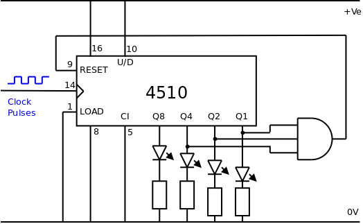 CLOCK receives the pulses to be counted
CI and LOAD are held LOW
U/D is held HIGH
The AND gate goes HIGH when Q1 = 1, Q2 = 1 and Q4 = 1 which corresponds to decimal 7. The output of the AND gate is connected to RESET and so the counter is immediately reset to zero when it reaches a count of seven. The counter counts from 0 to 6, on the 7th count it is reset to 0.
Example 2: Count from 1 to 6 and then start again
 Sometimes it is more useful to start counting from 1 rather than 0, when making a dice for example.
CLOCK receives the pulses to be counted
CI and RESET are held LOW
U/D is held HIGH
L1 is held HIGH and L2, L4 and L8 are held LOW. The four load inputs are held at the binary number 0 0 0 1 which is equivalent to decimal 1
The AND gate goes HIGH when Q1 = 1, Q2 = 1 and Q4 = 1 which corresponds to decimal 7. The output of the AND gate is connected to LOAD and so the counter is immediately loaded with the values at the load inputs, in this case 1. The counter counts from 1 to 6, on the 7th count it reloads the value 1 to the output.
Example 3: Count from 6 to 1 and then start again
 This is very much like example 2 but, as well as making the counter count down, the logic also needs to be changed. When the output is equivalent to decimal 0, the output must be reloaded with decimal 6
CLOCK receives the pulses to be counted
CI and RESET are held LOW
U/D is held LOW so that the counter counts down
L1 and L8 are held LOW, L2 and L4 are held HIGH. The four load inputs are held at the binary number 0 1 1 0 which is equivalent to decimal 6
The NOR gate goes HIGH when Q1 = 0, Q2 = 0 and Q4 = 0 which corresponds to decimal 0. The output of the NOR gate is connected to LOAD and so the counter is immediately loaded with the value decimal 6 on the outputs. The counter counts from 6 to 1, on the 7th count it reloads the value 6 to the output
Example 4: Count from 6 to 1 and then start again using Carry Out
 This is very much like example 3 but uses CO to reload the output with decimal 6
CLOCK receives the pulses to be counted
CI and RESET are held LOW
U/D is held LOW so that the counter counts down
L1 and L8 are held LOW, L2 and L4 are held HIGH. The four load inputs are held at the binary number 0 1 1 0 which is equivalent to decimal 6
As the counter counts down CO is HIGH and the output from the NOT gate is LOW. When the output reaches binary ZERO, CO goes LOW and the output of the NOT gate goes HIGH therefore LOAD goes HIGH and the output of the counter is immediately loaded with the value decimal 6. As soon as the output is loaded, CO goes HIGH and LOAD goes LOW so that the counter can continue to receive clock pulses.
At the time of writing there is a clear and concise tutorial about combining multiple counters (cascading) at EduTek
© Paul Nicholls
April 2019

Electronics Resources by Paul Nicholls is licensed under a Creative Commons Attribution 4.0 International License.