An amplifier is an analogue circuit. This page is about a voltage amplifier based on an Op-Amp. The output voltage (Vout) of the circuit depends on the input voltage (Vin) and the Gain (Av) of the circuit.
It is a good idea to read the amplifier basics page first.
For all the circuits shown below, the amplifier is assumed to have a positive and a negative power supply, usually ±15 V, so that the output voltage can be both positive and negative.
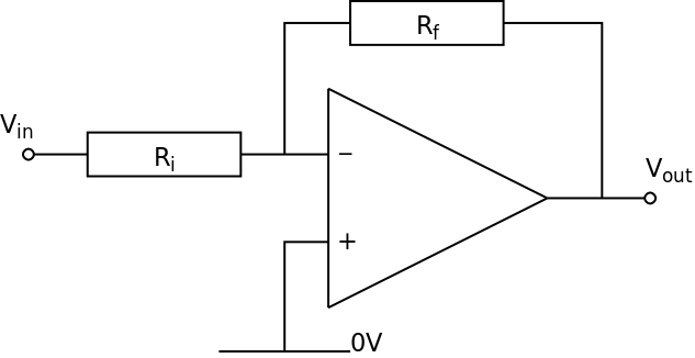
The Op-Amp needs to have ± power supplies (assumed to be ±15 V)
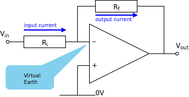
The non-inverting input is connected to 0 V
The circuit uses a feedback resistor (Rf) and an input resistor (Ri)
Voltage gain (Av) is determined by Rf and Ri
The voltage gain is given by:
The output voltage is directly proportional to the input voltage (as long as the output is not saturated) such that:
If the input voltage is positive, the output voltage is negative
If the input voltage is negative, the output voltage is positive
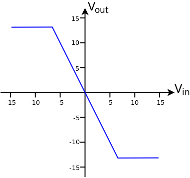 The graph shows the transfer characteristics (Input Voltage and Output Voltage) for an Inverting amplifier with a voltage Gain of −2
When Vin = +5 V then Vout = −10 V
when Vin = −5 V then Vout = +10 V
The Output Voltage is limited to ±13 V by the power supply of the amplifier. Therefore, when Vin > +6.5 V then Vout saturates at −13 V and when Vin < −6.5 V then Vout saturates at +13 V. The saturated output is shown by the horizontal lines on the graph.
 The graph shows the relationship between the Input Voltage and Output Voltage of an Inverting amplifier with a voltage Gain of −2 when the input is an A.C. voltage
At all times Vout = −2 × Vin
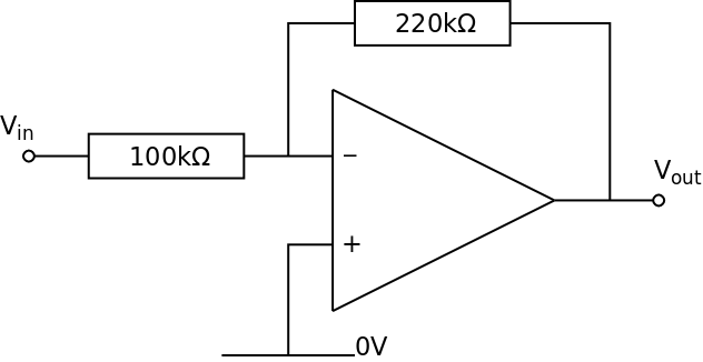 The voltage gain is:
If Vin = +1.0 V then Vout = −2.2 V
The Input Voltage has been amplified (made bigger)
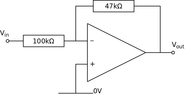 The voltage gain is:
If Vin = +1.0 V then Vout = −0.47 V
The Input Voltage has been attenuated (made smaller)
 The voltage gain is:
If Vin = +1.0 V then Vout = −1.0 V
This is a unit gain amplifier. The Output Voltage has the same amplitude as the Input Voltage. This amplifier is a buffer as the input takes almost no current from the voltage source but provides a reasonable current to the subsequent circuits
 The voltage gain is:
This is a poor circuit as the resistor values are too small. The amplifier will draw too much current from the source. Resistor values should always be greater than 1 kΩ
The two main parameters of the Inverting Amplifier are the gain and the bandwidth. Increasing the gain reduces the bandwidth and vice versa.
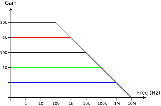 For an inverting amplifier based on a standard Op-Amp the relationship between gain and bandwidth is approximately:
The graph shows that as gain increases, bandwidth decreases. Note that both scales are logarithmic. The Gain axes shows the magnitude of the gain and the negative sign is ignored
When the gain is ×1 (blue line) the amplifier works effectively up to frequencies of 1 MHz
If the gain is increased to ×10 (green line) the amplifier only works effectively up to about 100 kHz. This is still suitable for audio
At a gain of ×1000 (red line) the amplifier only works effectively up to a frequency of 1 KHz before the gains starts to reduce and the Output voltage starts to decrease
If the gain is −100, the bandwidth is 10 kHz
If a bandwidth of 40 kHz is required, the maximum gain is −25
When used in reality, amplifiers are often decoupled which means that the input and output are connected through capacitors to stop any spurious D.C. signals compromising the performance of the amplifier. Depending on what circuit or transducer the amplifier is attached to, a resistor may also be needed on the output down to 0 V.
 The capacitor on the input is usually a non-electrolytic type, nominally 1 µF or less. The capacitor on the output is ideally a non-electrolytic type but sometimes larger value electrolytic capacitors need to be used if the amplifier is providing significant current to the next stage.
The addition of capacitors to the input and output can reduce the bandwidth of the amplifier.
When considering amplifiers made from Op-Amps there are two basic assumptions:
Negative Feedback
Gain Equation
We have
and therefore
© Paul Nicholls
October 2018

Electronics Resources by Paul Nicholls is licensed under a Creative Commons Attribution 4.0 International License.