Amplifiers are active (needing a power supply) devices that process analogue signals.
Analogue signals are signals that vary with time and can take any value between some maximum and some minimum value.
Analogue signals can be both positive and negative.
The purpose of an amplifier is to accept an analogue input signal and produce a copy of the signal at the output. The shape (quality) and frequency of the amplified input signal should not change at all at the output. Any change of shape is called distortion and is usually avoided as much as possible.
The amplitude of the output can be different from the amplitude of the input signal. The scaling factor is called the gain. If the resulting output signal is bigger than the input signal then it has been amplified. If the resulting output signal is smaller than the input signal then it has been attenuated. In both cases the change in the size of the signal is described by the amplifier gain.
The ideal amplifier can take an input signal of any amplitude, has an infinite input resistance so that no current flows into the input, has zero output resistance to provide as much current as necessary at the output and works equally well at any frequency. In reality, this is hard to achieve.
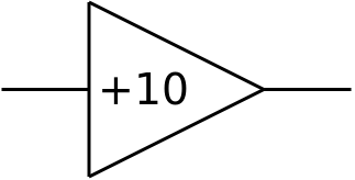 The symbol for an amplifier is very similar to that of a NOT gate and intentionally the same as a buffer. Be careful not to get them confused. The symbol shown is for a non-inverting amplifier with a gain of x10.
Amplifiers are considered in terms of:
In general terms, voltage gain is defined as: Voltage Gain = Vout / Vin
The voltage gain is purely a number being the ratio of two voltages. In real terms the voltage gain is the amount by which an input voltage is multiplied to give an output voltage

In almost all amplifier circuits the voltage gain is determined by external components such as resistors and capacitors rather than by the actual amplifier itself. This is achieved by providing feedback in just the right way (feedback is a topic to be considered in another section).
The open loop gain is the natural gain of the amplifier when no feedback is applied. This is usually very high.
The power gain is defined as the ratio of output power to input power: Power Gain = Pout / Pin
Power gain is most relevant when considering power amplifiers.
Distortion occurs when the output signal is not a true copy (albeit amplified or attenuated) of the input signal. The most common form of distortion occurs when the gain and/or input voltage are too high and the resulting output signal is (theoretically) greater than the maximum possible output voltage. The maximum possible output voltage is determined by the power supply voltages of the amplifier.
For example, a standard op-amp based amplifier has power supplies of ±15 V and a maximum output voltage of ±13 V. Consider an amplifier with a gain of +10.
For an input voltage of +1.0 V, the output voltage will be +10 V and the output is not distorted.
For an input voltage of +2.0 V, the output voltage will try to be +20 V but will be limited to +13 V. The input signal is distorted.
 In another example, an amplifier has a maximum output voltage of ±13 V shown by the dotted ORANGE line on the diagram.
The input voltage is ±5 V as shown by the BLUE line.
When the amplifier gain is +2, the output is ±10 V as shown by the GREEN line. This is less than the maximum output voltage and the input signal is amplified but not distorted.
When the amplifier gain is increased to +3 the output voltage should be ±15 V but it is limited to ±13 V by the power supply. The output is the RED line with the peaks of the output flattened off. The input signal is amplified but the output is not the same shape as the input. The output is distorted.
This form of distortion is called clipping.
Amplifiers behave differently at different frequencies, the capacitance of the feedback loop affects the gain and the actual characteristics of the amplifier components will also depend upon frequency. It is useful to know over what range of frequencies the amplifier works as planned, this is expressed as the bandwidth.
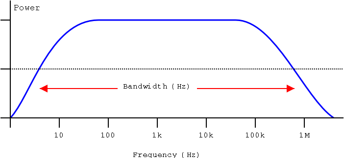
The bandwidth is the range of frequencies over which the amplifier circuit produces at least half of its rated output power
For example, an audio amplifier would have a bandwidth of at least 20 Hz to 20 kHz as this is the audible spectrum
Bandwidth is usually shown on a graph of frequency against power with either or one or both axes being logarithmic. A generic example of such a graph is shown below
It is important to realise that the bandwidth is expressed in terms of power. Recall that power can be expressed in terms of voltage and current, specifically P = V2 / R. Therefore we can also find a definition of bandwidth in terms of voltage. The power is proportional to V2 and so P/2 is proportional to ( V2 )/2 which implies that half power is achieved when the output voltage is reduced to V/(sqrt(2)) = 0.707 x V
The bandwidth is the range of frequencies over which the amplifier circuit produces at least 0.707 of its rated output voltage.
The bandwidth is the range of frequencies over which the voltage gain is greater than 0.707 of the expected voltage gain
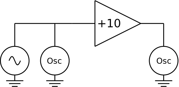 An amplifier can be tested using the circuit shown. A signal generator is connected to the input. This provides a signal of variable amplitude and frequency. One channel of a double beam oscilloscope is attached to the input so that the input voltage can be determined (usually kept fixed at a convenient value). The other channel of the double beam oscilloscope is connected to the output (which may or may not be connected to a load such as a loudspeaker) and is used to measure the output voltage.
To test the amplifier a range of frequencies is used. For an audio amplifier the frequencies used for testing might be 10 Hz, 20 Hz, 30 Hz, 50 Hz, 70 Hz and then 100 Hz, 200 Hz and so on up to 10 kHz, 20 kHz, 30 kHz, 50 kHz etc. This choice of frequencies gives a nice even spread on a logarithmic scale.
© Paul Nicholls
February 2015

Electronics Resources by Paul Nicholls is licensed under a Creative Commons Attribution 4.0 International License.