A binary counter counts clock pulses and the output is in binary.
A binary counter is made from D-type flip flops configured as divide by 2 counters because each output is worth twice as much as the previous one and therefore should require twice as many clock pulses to make it go HIGH. The outputs from the binary counter represent 0 when they are LOW and 1 when they are HIGH.
Note: When a binary number, such as 0111, is written down the LSB (Least Significant Bit) is on the right and the MSB (Most Significant bit) is on the left. Due to circuit building conventions, the output of a binary counter circuit has the LSB output on the left and the MSB output on the right hand side.
To help understand how a Binary Counter works it would be useful to read about the Divide by 2 Counter on the D-Type Flip Flop page and about Binary Numbers.
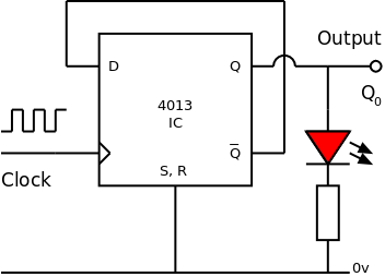 This counter can only count from 0 to 1 i.e. one clock pulse. After the circuit has been reset the output will be LOW. When 1 clock pulse has been received the output will be HIGH. The next clock pulse makes the output go LOW again. The output of the 1 Bit counter is Q0.
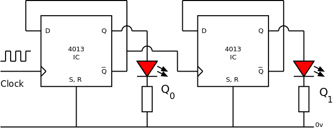 Important: The second divide by 2 counter must receive a rising edge clock pulse when the output of the previous counter goes from HIGH to LOW ... therefore the CLOCK of the second divide by 2 counter must come from the Q0 of the previous counter. If Q0 goes from HIGH to LOW, Q0 will go from LOW to HIGH which is the required rising edge.
 Initially Q0 and Q1 are LOW representing binary 0 0
On the 1st rising edge of the CLOCK, Q0 goes HIGH and Q1 remains LOW representing binary 0 1
On the 2nd rising edge of the CLOCK, Q0 goes LOW and Q1 goes HIGH representing binary 1 0
On the 3rd rising edge of the CLOCK, Q0 goes HIGH and Q1 remains HIGH representing binary 1 1
On the 4th rising edge of the CLOCK, Q0 goes LOW and Q1 goes LOW representing binary 0 0 and the count starts again.
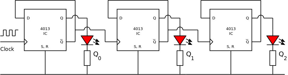 Extra Bits are added by adding extra divide by 2 counters with each counter being driven by the Q output of the previous counter.
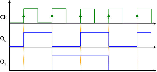
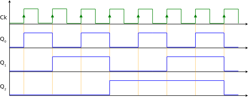 The timing diagram shows the state of the three outputs Q0, Q1 and Q2
Each output stays HIGH or LOW for twice as long as the previous output. With all the outputs starting LOW (as shown) it takes 8 (23) clock pulses to return back to the same state. A 3 Bit counter can count 8 clock pulses with the outputs representing binary 0 to binary 7.
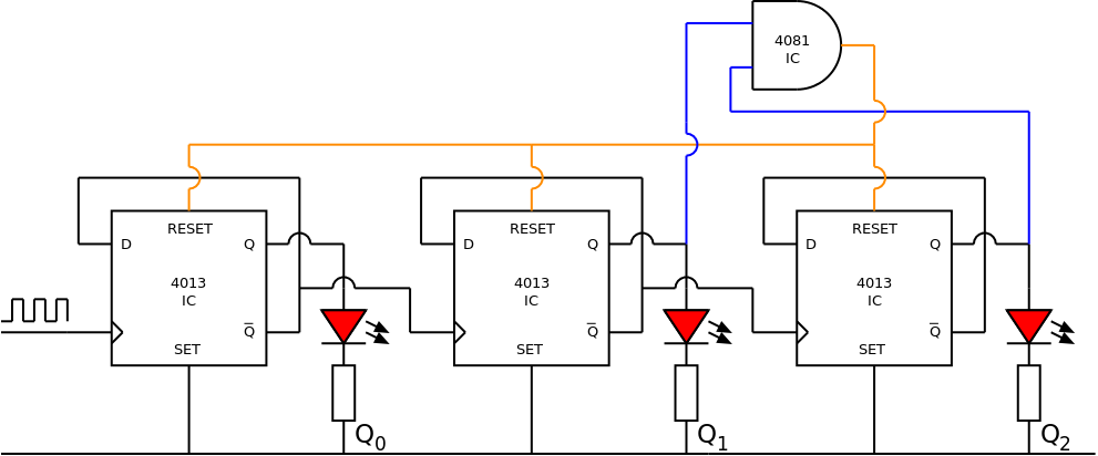 A 3 Bit counter will count 8 counts (from 0 to 7). To make the counter count to a smaller maximum value, use logic to RESET the counter at a particular value.
The circuit shown starts from 0 and counts to 5. On the next clock pulse the counter advances to binary 6 (1 1 0) such that Q0 is LOW, Q1 is HIGH and Q2 is HIGH. The output from the AND gate goes HIGH and immediately resets all the D-Type flip flops. The binary output 6 exists only as long as it takes the flip flops to reset.
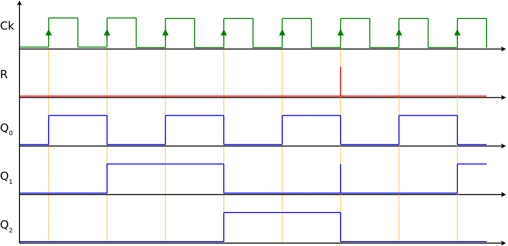 The timing diagram shows Q1 go momentarily HIGH which causes RESET go momentarily HIGH on the 6th rising edge of the clock. All outputs go LOW and the count resumes from 0 on the next clock pulse.
 The 3 input AND gate will give a HIGH output when the counter reaches binary 7 because Q0 is HIGH, Q1 is HIGH and Q2 is HIGH.
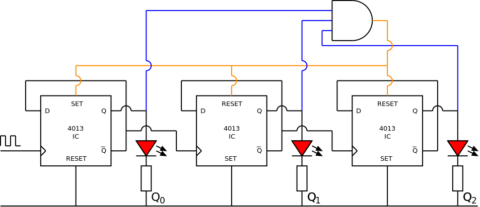
The output from the AND gate is connected to the RESET of the 2nd and 3rd counters but connected to the SET of the 1st counter. When the output of the AND gate goes HIGH, Q0 immediately becomes HIGH and Q1 and Q2 are immediately made LOW. The count restarts at binary 1.
In this example, logic gates are used to LOAD binary 1 into the counter which then counts to binary 6 before re-loading binary 1 on the next clock pulse. The counter repeatedly counts from 1 to 6 which is useful for making a dice.
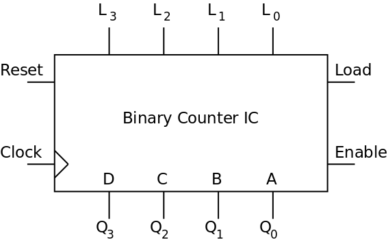 Binary counters are available as an all-in-one IC such as the generic counter shown in the diagram.
The outputs Q0 - Q3 are sometimes labeled A, B, C and D
Making the LOAD input momentarily HIGH loads the 4-Bit binary word on L0 - L3 onto the outputs Q0 - Q3
RESET returns the all the outputs to LOW.
EN (Enable) or CI (Clock Inhibit) stops the counter from responding to clock pulses but does not reset the outputs.
On the diagrams and in the text the outputs are represented as Q0, Q1, Q2 and Q3 etc.
On other web pages, resources and textbooks the outputs are represented as Q1, Q2, Q4 and Q8 etc.
The two conventions are equivalent:
Q0 → Q1 representing 1 (20)
Q1 → Q2 representing 2 (21)
Q2 → Q4 representing 4 (22)
Q3 → Q8 representing 8 (23)
© Paul Nicholls
April 2018

Electronics Resources by Paul Nicholls is licensed under a Creative Commons Attribution 4.0 International License.